< Return to insights hub
- November 12, 2026
Guide to connecting SF20/C and LW20/C for EMI protection
Electromagnetic interference (EMI) is a common problem when integrating LiDAR into systems that include motors, radios, ESCs, power distribution boards, or high-current wiring. EMI can disrupt signals, degrade accuracy, and, in some cases, cause sensor dropouts.
This guide outlines best practices for wiring, grounding, shielding, and power management to help ensure reliable operation of the compact, ultra-light LightWare microLiDAR® SF20/C and LW20/C sensors in EMI-prone environments.
Impact of EMI
In UAV and robotics systems, EMI often originates from brushless motors, high-power ESCs, RF transmitters and telemetry radios, DC-DC converters, and power wiring running close to data lines.
LiDAR systems affected by EMI tend to present noisy data and unstable readings, communication errors, reduced update rates, and even complete sensor dropouts in extreme cases.
This is where LightWare’s microLiDAR® SF20/C and LW20/C sensors are in a different class. When connected correctly using EMI mitigation techniques, these symptoms are rarely seen, ensuring a high level of reliability.
Recommended Wiring and Connection Practices
Use Twisted Pair Wiring for Critical Signals
Communication signal lines, such as I²C (SDA and SCL) and UART (RX and TX), should be routed as twisted pairs where practical, particularly when the sensor is near high-noise electrical components. This reduces noise coupling and improves signal integrity and overall system reliability.
Keep Power and Signal Lines Separate
Route microLiDAR® signal wires away from high-current power lines, ESCs, and battery cables. Avoid running data lines parallel to power wiring for long distances.
Use Short Cable Lengths
Since long cables can behave like antennas, cables should be kept as short as possible, ideally under 30 cm for most UAV setups. I²C is more susceptible to noise over longer cables, so if a longer cable is unavoidable, use serial UART instead.
Proper Grounding
Floating grounds can amplify noise and induce erratic readings. This means that sensor ground, controller ground, and power supply ground must share a common reference.
Avoid ground loops, which occur when the sensor is grounded through more than one path (for example, through both its cable and a metal mount). These loops pick up interference from nearby motors and power wiring. To avoid this, connect all grounds back to a single common point.
Add Ferrite Cores for High-noise Installations
Ferrite beads suppress high-frequency interference. They should be placed near the sensor end and the controller end of the cable.
Power Supply Considerations
Clean and Stable Power Input
Use noise filtered or regulated 5 V supplies. Avoid sharing a supply rail with motors or servos.
Using DC-DC converters
If converters are necessary, shield them and position them away from the sensor to minimize EMI.
Mounting and Mechanical Considerations
Placement on the Platform
Keep the sensor physically separated from motors, ESCs, and RF antennas. A distance of at least 10 to 15 cm from major EMI sources is recommended.
Shielding Options
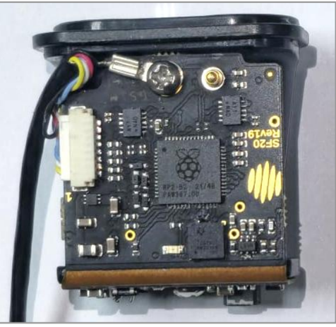
For the SF20/C, consider conductive shielding for additional protection, but make sure the shielding does not cover any part of the optical apertures.
If an enclosure is designed for the SF20/C, there should be proper grounding between the PCBA and the enclosure.
Avoid vibration
Excessive vibration can mimic noisy signals. Soft mounts are recommended but avoid mounts that allow orientation drift.
Testing and Validating EMI Protection
Testing is an important step when validating sensor integration in electrically noisy systems.
- Baseline Testing: Collect microLiDAR® data with motors powered off to establish a noise-free benchmark.
- Controlled tests: Run motors at different throttle levels and monitor spikes, dropouts, or reduced update rates.
- Review Data Logs: Readings consistent with your baseline indicate proper EMI mitigation.
- Advanced Tips for High-noise Environments
In particularly challenging environments, the following additional steps may help:
- Use shielded cables for long installations.
- If the sensor or wires are placed near brushless motors and electronic speed controllers, which produce medium- to high-frequency noise, the cable shielding must be terminated at both ends.
- Add grounding straps to metal frames where possible.
- Reduce sensor update rates for better noise immunity.
Key Similarities and Differences Between the SF20/C and LW20/C
Both sensors share LightWare’s core time-of-flight technology and support serial and I²C communication. They can also be integrated with DroneCAN using the DroneCAN adapter.
These EMI best practices apply to both sensors. The LW20/C’s enclosure provides built-in protection, while the SF20/C’s open-frame design leaves cable routing and shielding to the integrator, so following these practices is especially important.
| Similarities | Differences Relevant to EMI Protection |
|---|---|
| 100-meter ranging | LW20/C: Includes an IP67-rated enclosure that acts as an EMI shield and a heat sink. |
| High accuracy and fast update rates | SF20/C: OEM sensor with an open-frame design, requiring extra attention to cable routing, shielding, and heat management. |
| Flexible integration options |
Both sensors share LightWare’s core time-of-flight technology and support serial and I²C communication. They can also be integrated with DroneCAN using the DroneCAN adapter.
These EMI best practices apply to both sensors. The LW20/C’s enclosure provides built-in protection, while the SF20/C’s open-frame design leaves cable routing and shielding to the integrator, so following these practices is especially important.
Your Next Steps for a Successful Connection
Proper wiring, grounding, shielding, and testing are essential for reliable LiDAR performance in EMI-heavy environments. Both LightWare’s microLiDAR® SF20/C and LW20/C sensors are engineered for high-performance use when connected correctly.
Visit the LightWare Resource Center for wiring diagrams and integration guides, or contact LightWare for project-specific EMI consultations.

Blog written by
Mohit Morar
Mohit Morar is a Technical Support Manager specialising in helping customers successfully integrate LiDAR sensor solutions across both hardware and software environments. With a background in Mechatronics Engineering, a Master’s degree in Electrical Engineering, and an MSc in Control Engineering, Mohit brings a strong multidisciplinary technical foundation to his role.
Prior to joining the LiDAR industry, Mohit worked at Thyssenkrupp in the EC&I department, supporting mining machinery upgrades and maintenance. This experience provided him with valuable exposure to complex industrial systems and practical engineering challenges.
Known for his level-headed, respectful, and helpful approach, Mohit is passionate about understanding technical challenges and working collaboratively with customers to find practical, effective solutions
Never miss a story
Stay updated about LightWare news as it happens.