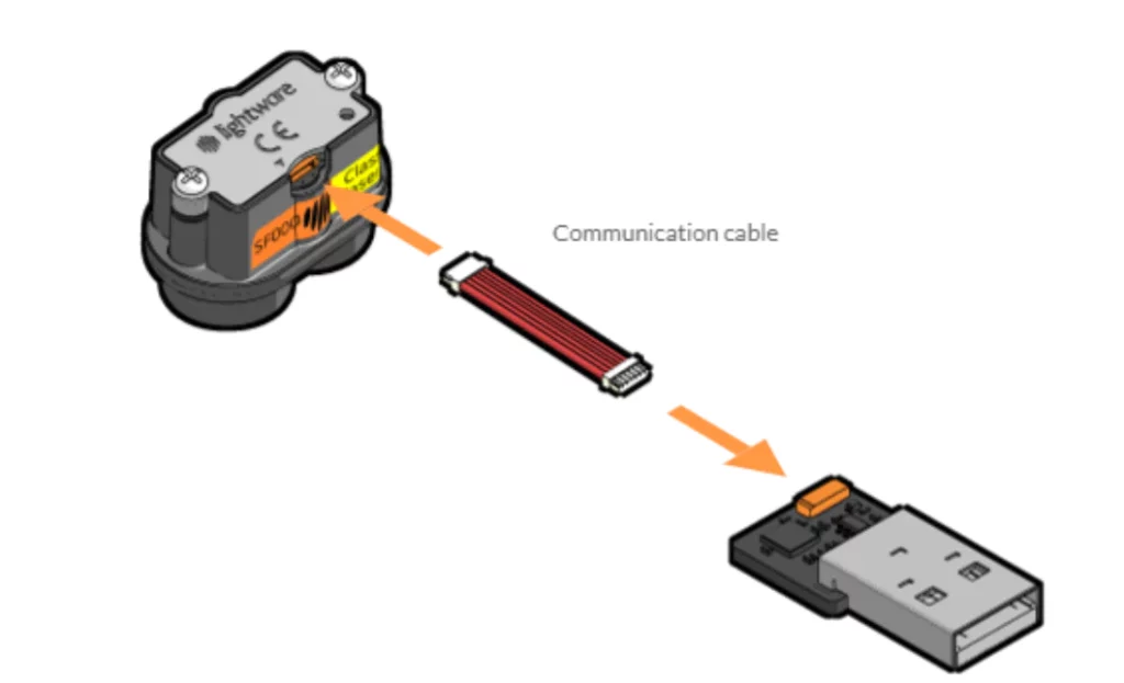
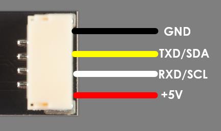
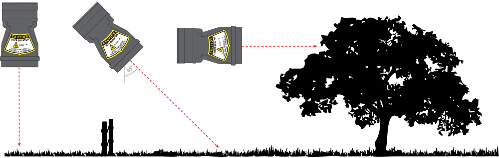
________________________________________________________________________________________________________________________________________________
Code:
// www.Lightware.co.za Oct 2019
// Lightware example code using the lw_sf22.h library
// This library enables the use of the I2C and Serial Interface
// This library is designed to use 2 Serial ports on the Arduino
#include <lw_sf22.h>
#include <Wire.h>
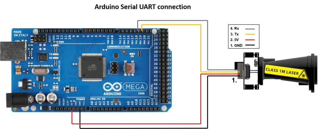
LW_SF22 sf22(Serial1, Serial);
void setup() {
//this is the serial port for the terminal window
Serial.begin(115200);
// Setup the Serial port for the SF22 interface
Serial1.begin(115200);
// Disable any possible streaming data
sf22.writeDataStreamType(0);
delay(100);
// Read the data sent from the SF22
sf22.ProcessSerialInput(1);
delay(100);
// Request the SF22 Hardware Name
sf22.readRequestHardwareName();
delay(100);
// Read the data sent from the SF22
sf22.ProcessSerialInput(1);
delay(100);
// Request the SF22 Firmware Version
sf22.readRequestFirmwareVersion();
delay(100);
// Read the data sent from the SF22
sf22.ProcessSerialInput(1);
delay(100);
// Request the streaming output distance data selection
sf22.readRequestDistOutConfig();
delay(100);
// Read the data sent from the SF22
sf22.ProcessSerialInput(1);
delay(100);
// Set the streaming to distance in cm
sf22.writeDataStreamType(13);
delay(100);
// Read the data sent from the SF22
sf22.ProcessSerialInput(1);
}
void loop() {
uint8_t new_data = 0;
// Every cycle check the Serial receive buffer for data and then process it
new_data = sf22.ProcessSerialInput(0);
// if new data was received, then display the following first and last distance
if (new_data == 1){
Serial.print(sf22.firstRaw_cm,DEC);
Serial.print(” cm “);
Serial.print(sf22.firstStrength_cm,DEC);
Serial.print(” % “);
Serial.print(sf22.lastRaw_cm,DEC);
Serial.print(” cm “);
Serial.print(sf22.lastStrength_cm,DEC);
Serial.print(” % “);
Serial.print(sf22.APDTemperature,DEC);
Serial.println(” DEG Celcuis “);
new_data = 0;
}
// put your main code here, to run repeatedly:
}
________________________________________________________________________________________________________________________________________________
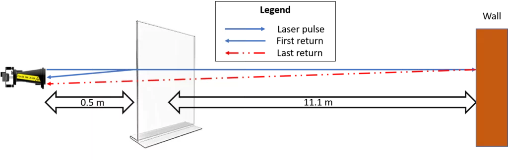
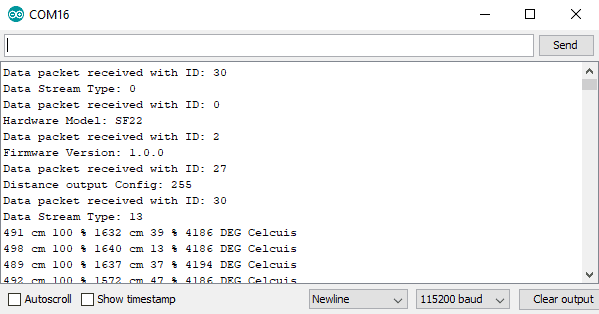
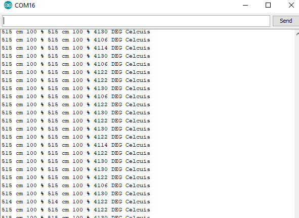
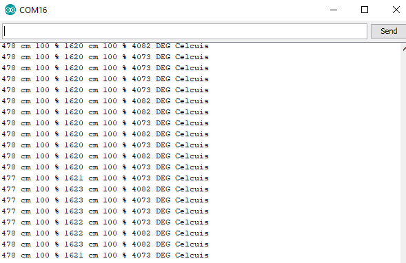
Results :
The results are printed in the following sequence
- First Return
- First Signal Strength
- Last Return
- Last Signal Signal Strength
- APD temperature.
Initial Startup: